
-
- Making New Roof Ventilators
- By Nick Webster
-
- Click on photos to see an enlargement
| This article is about how I made roof ventilators
for my 1957 Harrington bodied Dennis Lancet UF. The ventilators originally
fitted were a bought in item from a firm called Rawlings and were no doubt
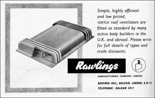
used by a wide variety of coachwork manufacturers. I found an old advertisement
that shows that they were available in two sizes. I deduced this from the
number of ventilation "gills" fitted to the vent pictured in
the advertisement and those remaining on the vents fitted to my bus. There
were eight in the advert and only six on mine. At first I wondered if two
of mine had fallen off. Then I saw another picture that confirmed that
the "eight gill" type was altogether bigger. Which was a bit
of a relief because I had already recognised that making these replicas
was going to be a rather mind numbing repetitive job at times. Especially
as someone else I know made me an offer I could not refuse to make him
one as well while I was at it.
|
-
| 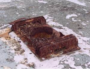 When
I first climbed up the ladder to the roof of YYB 118 this was the sorry
sight that met my eyes. There were supposed to be three vents fitted to
the roof but all of them were in a very poor state. They are made of steel
and as a consequence of being riveted to the aluminium roof had come off
worst. When
I first climbed up the ladder to the roof of YYB 118 this was the sorry
sight that met my eyes. There were supposed to be three vents fitted to
the roof but all of them were in a very poor state. They are made of steel
and as a consequence of being riveted to the aluminium roof had come off
worst.
Naturally I asked around just in case these things were a stock item
somewhere, but sadly, no. Not that this was a surprise. Someone said that
he thought he had seen non working replicas made in fibreglass, but it
seemed to me that there was some advantage in having working vents and
they looked of fairly simple construction. The picture in the advert was
even "cut away" to give an idea of how they might work. Furthermore
replicas could be mostly made from aluminium off cuts with the bases cut
from between the dents on old replaced body panels. |
-
| 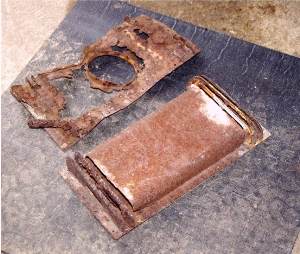 I
removed the old vents for patterns and here is a picture of the best and
worst. I could just about glean enough information to use for my replicas. I
removed the old vents for patterns and here is a picture of the best and
worst. I could just about glean enough information to use for my replicas.
The first job was to make a die to form the "gills". This
was a piece of scrap steel. Well two bits actually because you need to
sandwich the aluminium between them. This is what is going on in the picture
below. One of the dies is very slightly smaller than the other to enable
me to get in close and bash the aluminium tightly over the correct sized
former. The small one has the X on it so I can tell the difference. It
also identifies the outside of the die because my filing is not quite uniform! |
-
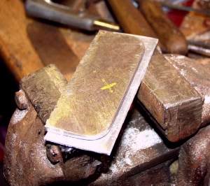 Not very
clear in the photo of the die is the small slot just about half an inch
up from the bottom on both ends. This represents the place where a bend
in the aluminium will be. Because I made up the die from the scruffiest
bit of scrap I could find the bottom edge was not very regular and all
my measurements had to be taken from the top edge. Someone less mean than
I could probably do this more easily by starting with a straight edge!
A regular bottom edge would also help in setting up the aluminium visible
around the outside of the die, whereas I did by eye each time. |
-
| 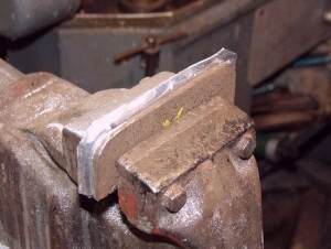 This is forming the "gill"
by simply knocking the surplus aluminium edge over the large die with a
small hammer. Note that I have already snipped the sharp corner off. Don't
try and bash it all at once - bend it part way all the way around and then
go back again. This is forming the "gill"
by simply knocking the surplus aluminium edge over the large die with a
small hammer. Note that I have already snipped the sharp corner off. Don't
try and bash it all at once - bend it part way all the way around and then
go back again.
This assumes you are using nice soft aluminium of course. As I have
already said, these small projects lend themselves to scraps you have hanging
around, so you may need to soften older material which has age hardened.
For general purposes (and without recourse to the slightly superior method
of using acetylene soot) the best way to soften aluminium is to use soap
as an indicator. Decent basic hard soap is getting so hard to find but
I find Fairy Household to be quite good. Failing that, the small tablet
you get in a Travel Lodge is not bad, but alas, even they are going over
to liquid soap these days. Just scrawl on the aluminium as if you were
using a crayon. You do not have to cover it all; here and there will do.
Now apply heat using a decent sized blow torch. As the temperature rises
the soap, previously pretty much invisible until now will start to turn
brown and finally black. Job done. The melting point of aluminium is a
mere 660 degrees C. so do not apply any more heat after the soap turns
black unless you wish to move on to metal casting for beginners. Leave
the aluminium to cool by itself and don't pick it up until it is cold. |
-
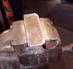 After
the aluminium had been knocked around the die, using a junior hacksaw I
cut little slots in the edge, referencing the slots cut in the edge of
the die. This marks the place for a bend to form the foot for the gill.
Then, mounting the die flat in a vice I filed off the surplus aluminium
until it was flush with the die. I have to confess - you remember I marked
the smaller die with a "X", well at first I marked the larger
die and then promptly filed off most of the "X" with the first
one I made. This is why you can see a yellow X in the photo right, but
it is not the mark; it is a mark. Ahem. |
-
| 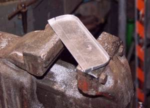 This is
the gill extracted from the die, with a score mark between the slots to
indicate where I am going to bend it later. Which as you can see was carefully
done by putting it in a vice and hitting it. Again, if I had taken more
care (and time) making my dies I could probably have bent the aluminium
while it was held between them. There was a certain amount of making it
up as I went along and in the end the tab for the foot (which was intended
to simplify spacing the gap between the gills) turned out to be slightly
too generous and had to be trimmed down to size. This is
the gill extracted from the die, with a score mark between the slots to
indicate where I am going to bend it later. Which as you can see was carefully
done by putting it in a vice and hitting it. Again, if I had taken more
care (and time) making my dies I could probably have bent the aluminium
while it was held between them. There was a certain amount of making it
up as I went along and in the end the tab for the foot (which was intended
to simplify spacing the gap between the gills) turned out to be slightly
too generous and had to be trimmed down to size.
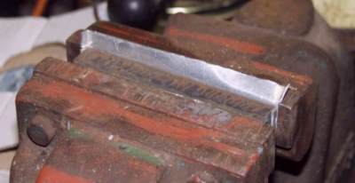
At length… And I mean at length because
I could not face doing all of them in one go, you end 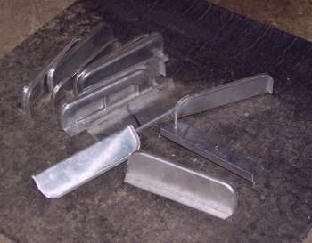 up
with a whole pile of the little beggars, as seen in the photo. This is
enough for two vents. Sigh…only twelve more to make to complete the
set. One of them is my prototype which is why it already has holes cut
in it. up
with a whole pile of the little beggars, as seen in the photo. This is
enough for two vents. Sigh…only twelve more to make to complete the
set. One of them is my prototype which is why it already has holes cut
in it. |
-
| 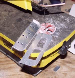 The prototype holes were completely
filed by hand and I fiddled around with various alternative ideas when
I realised doing the whole lot with a file was just not on and inventing
a punch press was equally ridiculous. Eventually I decided to cut them
out using a fret saw. Fortunately I have a power one of these which I originally
bought for cutting out thin plywood parts when making seat carcases, but
it has turned out to be really useful for many bus preservation jobs. The prototype holes were completely
filed by hand and I fiddled around with various alternative ideas when
I realised doing the whole lot with a file was just not on and inventing
a punch press was equally ridiculous. Eventually I decided to cut them
out using a fret saw. Fortunately I have a power one of these which I originally
bought for cutting out thin plywood parts when making seat carcases, but
it has turned out to be really useful for many bus preservation jobs.
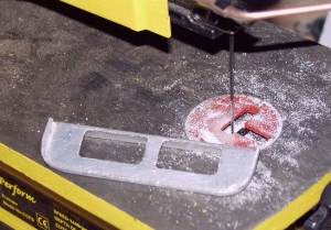
I made an aluminium template to mark out where the holes would go. At
first I thought I had made a mistake by bending over the foot of the gill
before I reached this stage. Then I realised the piece was easily supported
with a block of wood to hold it flat for cutting and more importantly,
since the bend was already in place it enabled me to gauge the cutting
to leave a very slight lip just above it which made the whole thing much
stronger. You can just about make this out in the next photograph. I did
try bending one after the holes were cut and it distorted.
 |
-
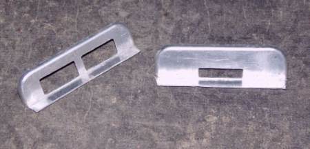
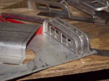
| Fortunately, not all of the gills require so much cutting. The small
hole is the air inlet which faces towards the front of the bus. There are
four of the other 2 hole gills, two each side of the centre section and
the final one at the back of the whole assembly is a blank.
 |
-
|  The base plate was made simply by copying
the size of the steel original. I did not have a hole cutter of the right
size so this was roughly cut and then filed to the correct size. Often
the right tool is available to buy but at such a price that you would have
to make dozens to make it pay, so I have a good selection of files which
are useful for all sorts of stuff. The base plate was made simply by copying
the size of the steel original. I did not have a hole cutter of the right
size so this was roughly cut and then filed to the correct size. Often
the right tool is available to buy but at such a price that you would have
to make dozens to make it pay, so I have a good selection of files which
are useful for all sorts of stuff.
You have to fasten the gills at one end only and then fasten the centre
section next. Due to the curve on the gills, the centre cannot be fitted
if all the gills are in place.
The centre section was bent in a small bending machine mounted in a
vice and then while the edge was still held in place the curves were put
in "freehand" by bending round a steel bar, which was clamped
on and packed to the right height. There were a couple of rejects before
I got everything symmetrical and the radius quite right. Once one was ok
I made a cardboard template (good old Kellogs) so that I could mark out
on a flat sheet correctly each time. Of course if I was a proper tinsmith
I would have made the template first, but calculations are all very well
but somehow don't always translate to the real thing easily. In fact, if
I was a proper tinsmith I would have got it right first time even without
calculations. |
-
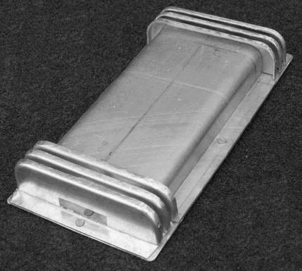
This is the finished article. There is a 3 inch diameter tube that goes
through the hole in the roof of the bus and the ventilator base plate.
This must stick up proud or water will find its way inside the bus from
rain driving into the air inlet. I made the tube by bending aluminium sheet
and sealed it in place with automotive mastic, which is all the fastening
it needs.
The original Rawlings ventilators were spot welded together. Spot welders
are not usually found in the home workshop and one capable of handling
aluminium is even less likely. I turned down an offer to TIG weld the gills
in place, partly because it meant someone else aligning all my bits and
in line with my motto of "made it all myself so far" settled
for using solid aluminium rivets.
The base plate was prepared using a 120 degree countersink and the small
excess of rivet ground off, leaving a smooth underside to the ventilator
which will sit down nicely on the roof of the bus. The interior gills had
three rivets each but anything with an outside edge only had the minimum
required to hold it in place because of course eventually pop rivets will
be used all around to fasten the complete assembly to the bus.
So there we are. They were made out of scrap off cuts and do have a
bit of a hand made look. They don't have "Rawlings Vortex" embossed
in the top of course. Better than my original thought which was to plate
over the offending holes in the roof. And I reckon it is going to be quite
some rivet counter who can find fault with them once they are fixed in
position up on top.

|

 Newsletters
Index Newsletters
Index
 Back to Index Back to Index
-
- © Copyright by Dennis Society, All
Rights Reserved.
|